with permission) Smith et al (g) in 2015 proposed adoption of Dunworth’s “generalised method’ of inclining analysis.")
By Rob Gehling, FRINA
Background
As a naval architecture student, I was taught that the metacentre was applicable only at zero angle of heel, irrespective of its role in determining the initial slope of the righting lever curve. But it can be easily proven that the metacentre moves around at small angles of heel and may not be on the centreline even for wall-sided symmetrical vessels. Plots of the vertical and transverse position of the metacentre often show that the metacentre can move vertically and off the centreline.
The lightship characteristics measured by inclining experiment are a fundamental input to managing a ship’s intact and damage stability throughout its service life or until it is re-inclined. In the latter case, considering that stability may deteriorate during the life cycle, informed decisions based on accurate GM measurements could feed back into design and operation for better stability management or indeed better designs.
It is, therefore, timely to re-examine the traditional inclining experiment analysis methods, taking account of the technological developments and tools now available to naval architects compared with those when I first inclined a ship in the early 1970s. My experience back in the 70s and 80s in inclining and reviewing reports for merchant ships could be summarised by the lightship VCGs of bulk carriers and single hull tankers up to 150,000dwt having a range of up to 10% depth, with no particular reason for the variation. These vessels were inclined in as light draught as practicable and under very tight checks on the consistency of GM measurements resulting from each weight movement. While these ships were generally very stiff from an intact stability perspective, the accuracy of measuring the lightship VCG from the inclining experiment may have been marginal from the broader safety perspective. A specification under which these inclining experiments were conducted drew attention not only to minimising “items on” and “items off” to obtain the lightship but also in changing the waterline such as by immersion or emersion of chines.
The importance of an accurate VCG with regard to damage stability has increased in recent years through amendments to SOLAS and MARPOL.
The wall-sided assumption that underpins the traditional GM method of analysing outcomes of experiments can be disproven by calculating the location of the transverse and vertical centres of buoyancy and applying the BM = I/Vol formula as the vessel is inclined.
Current developments
We now have computer modelling and calculation tools available to us for accurately tracking hydrostatic characteristics and the KN value at all stages of inclining. Most hydrostatic packages are no longer limited to moulded lines but can take account of hull thickness to provide more accurate hydrostatics. We no longer have to use free surface moments to track the centres of gravity for liquids on-board as the vessel heels, as computer models can similarly track these.
Commencing with his paper ref. (a) to the Pacific 2013 International Maritime Conference, and an expansion of that paper (b) in 2014, Dunworth has advocated for almost a decade for a change in the analysis of outcomes of inclining experiments to be based on KN values rather than classical GM. This method, later referred to by Karolius and Vassalos (d) as the “generalised method”, was described by (a) to provide reliable results for a proa hull form as a demonstration of its satisfactory application to asymmetric forms, centre of gravity off-centreline and changes to underwater geometry during inclining such as immersion/emergence of multihulls. The relevant hull form is reproduced here as Figure 1. In his second paper (b), Dunworth used the hull section model (HSM) to explore a range of inclining experiment scenarios on a hard chine craft, a theme that was further extended, including experiments with inclining in air in his most recent paper (c) in November 2021.
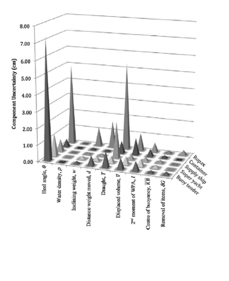
Figure 2. Component uncertainty contribution in the vertical location of the centre of mass for various inclining experiment parameters for the five case study ships (reproduced from (h) with permission)
In 2016 Woodward et al (h) published an assessment of inclining experiment parameters for five case-study ships of different types. The relevant diagram is reproduced with permission as Figure 2 and shows that the areas of greatest uncertainty are with the measured heel angle (for a ropax and buoy tender) and draught (for ropax). The figure was also reproduced in (d) whose authors extended the work to consider alternative methods of determining lightship characteristics in the diagram reproduced as Figure 3 which indicates an order of magnitude inaccuracy in VCG from the classical method compared with the alternatives.
In my view the problem with accuracy of angle of inclination could be improved by paying increased attention to its measurement. Possible measures include using multiple pendula, U-tubes (while attractive in terms of a U-tube across the breadth of a ship may be equivalent to a very long pendulum my experience is that viscous effects may result in reduced heel angles compared with pendula), midship draught measurement after each weight movement particularly for multihulls and apps or other electronic devices.
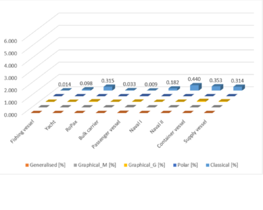
Figure 3. Percentage error for VCG, 2 degrees maximum heel angle and 0 degrees initial heel angle (reproduced from (d) with permission)
Apart from demonstrating the above-mentioned point with regards to movement of the metacentre, (d) provides an analysis of the accuracy of the various available methods of determining lightship characteristics, showing that the traditional classical GM method is at least an order of magnitude less reliable than the generalised, polar, and graphical methods.
The papers referred to above, when taken together, conclusively demonstrate that the classical method of analysing the outcome of an inclining experiment “will generally result in an incorrect VCG” as stated in (c). In it Dunworth notes that IMO’s Intact Stability Code (IS Code) (e) specifies in paragraph 2.22 of its introduction that the VCG can be determined “by applying basic naval architecture principles” to the information from the inclining experiment. Further guidance might be expected from the IS Code’s Annex 1 (f) but this document is only written in general terms. So paragraph 2.22 is likely to be interpreted to refer to the classical (GM) method. But in light of the information provided in the referenced papers and the assumptions involved in the classical method, paragraph 2.22 should more correctly be taken (and amended) to refer to the generalised (KN) method as that method more correctly reflects “basic naval architecture principles”. Accordingly, in (c) Dunworth questions whether continued and unquestioning use of the classical GM method would be consistent with RINA’s Code of Professional Conduct requirements, which are specifically for each member to:
“so order his/her conduct as to uphold the dignity and reputation of his/her profession: and to safeguard the public interest in matters of safety and health and otherwise”.
The generalised method should therefore be used in place of the classical GM method and any legislated requirements requiring use of the classical GM method should be amended to permit use of the generalised method in the public interest.
Conclusions
Since the generalised method has been proven much more accurate on a wide variety of hull forms, I would expect that, as an extension of what has already been demonstrated on a proa and chined vessels, the method will be proven to produce good results on all types of hull forms, including for example trimarans with surface-skimming side hulls, where the immersed body varies markedly as the vessel heels.
On the other hand, I would also expect that the generalised method might not produce markedly better results on a large catamaran high-speed craft, where the GM value may be in excess of 100m, since the variability of the intersection point for the various KN lines applicable during the experiment is likely to be substantial compared with the vessel’s depth.
Based on the above summary of papers on this subject, there are compelling reasons for all naval architects and regulators to adopt the generalised method, particularly for vessels whose waterplane may change to any significant extent across the range of heel experienced during an inclining experiment. These reasons are:
- Lack of reliance on the metacentre being falsely assumed to be a single stationary point through which the buoyancy is assumed to act during the experiment;
- Lack of reliance on the centre of gravity being on the centreline;
- Catering for asymmetric hull forms;
- Avoiding the wall-sided assumption by catering for immersion/emersion of chines, side hulls and so on; and
- Taking advantage of improved accuracy provided by the capabilities of modern naval architectural software packages.
Even in such cases where the wall-sided assumption remains valid, the generalised method should be treated as at least equivalent to the classical method.
This article has been developed from that published in the April 2022 issue of The Naval Architect.
Finally, our profession should thank Richard Dunworth and Prof Dracos Vassalos for their perseverance in bringing this important practical subject to attention. The significance of references (a) and (c) has been recognised through Walter Atkinson Award for 2014 and 2022 being presented to Richard Dunworth for the best written paper published by or presented under the Australian Division of the Royal Institution of Naval Architects in the 12 months to 30 June of those years.
REFERENCES
(a) Dunworth RJ, Back Against the Wall, Pacific 2013 International Maritime Conference, Sydney, and reproduced in The Australian Naval Architect, February 2014, pp30-35
(b) Dunworth RJ, Beyond the Wall, 12th International Conference on the Stability of Ships and Ocean Vehicles, Glasgow, June 2015
(c) Dunworth RJ, Scaling the Wall; Inclining Experiment Analysis on Vessels with Chines, Hull Discontinuities or Asymmetry, The Australian Naval Architect, Sydney, Australia, November 2021
(d) Karolius K B & Vassalos D, Tearing down the wall – The inclining experiment, Ocean Engineering no.148, Jan 2018
(e) International Maritime Organization: International Code on Intact Stability 2008, IMO Res. MSC.267(85)
(f) ibid, Annex 1 – Detailed Guidance for the Conduct of an Inclining Test
(h) Smith AC, Dunworth RJ & Helmore PJ, Towards the Implementation of a Generalised Inclining Method or the Determination of the Centre of Gravity, Pacific 2015 International Maritime Conference, Sydney, Australia
(i) Woodward MD, van Rijsbergen M, Hutchinson KW & Scott A, Uncertainty analysis procedure for the ship inclining experiment, Ocean Engineering 114 (2016), pp79-86
About the Author – Rob Gehling
On graduation in naval architecture in 1973 from the University of New South Wales, Sydney, Rob commenced his career as a design engineer at the Whyalla Shipbuilding and Engineering Works, builders of Australia’s largest commercial ships. In addition to design work, he undertook all types of naval architectural calculation work on ships under construction, including the conduct of inclining experiments and preparation of stability data.
With the shipyard closing in 1978 he joined the Department of Shipping and Transport in Melbourne, his main task being scrutiny of inclining experiment reports and stability data presented for regulatory approval. The organisation changed its name several times and moved to Canberra in 1982, becoming the Australian Maritime Safety Authority. Rob’s role also changed to move into ship design and construction regulatory matters as Chief Naval Architect and Manager Survey Planning & Development. He became Australian delegate to the International Maritime Organization’s Sub-committees on Ship Design & Equipment (DE) and Stability Load Lines & on Fishing Vessel Safety (SLF). He headed the working and drafting groups that drafted the International Code of Safety for High-Speed Craft in 1992-94 and was involved in its further development through to 2008. Rob chaired the SLF Sub-committee from 2005 to 2010.
A member of RINA’s Safety Committee since 1998, member of Council, past President and currently Secretary of the Australian Division, Rob has prepared this article on inclining experiments in furthering the Safety Committee’s efforts to improve maritime safety.